CM5 MEZZANINE · CELLULAR + GNSS

Give a CM5 cellular and GNSS — lose nothing else

A small module that gives a Raspberry Pi Compute Module 5 cellular and GNSS without taking anything away from it. 198 of 200 pins pass straight through; the only exception is UART4, which either the CM5 or your carrier board can own.

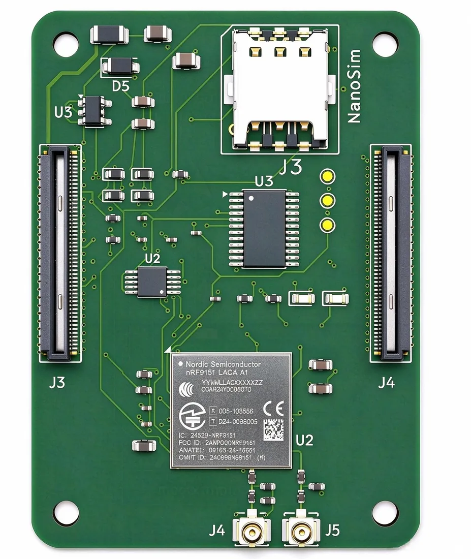
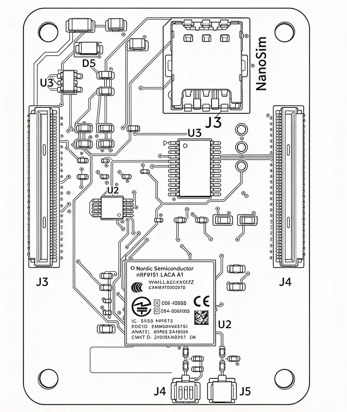
MEZ-CM5-NRF9151-V1.2 40 × 55 × 0.8 mm J1 plug → CM5 / J2 receptacle → carrier

Product overview

Q.MINI CM5-9151 is built to the Raspberry Pi Compute Module 5 (CM5) connector standard and sits between the CM5 and your carrier board. All 200 pins arrive; 198 pass straight through, six radio nets run at 50 Ω, and the only signal that leaves the direct path is UART4 — routed through an analog switch so the CM5 and the carrier board can each own it. The board also stands alone: with no CM5 fitted, a carrier-board MCU owns that same UART4 port, and for simpler products the nRF9151 can run the control logic itself — a communications node, or the core controller, without a separate host. Board figure MEZ-CM5-NRF9151-V1.2.

  • 200Pins on the bus
  • 198 / 200Straight through
  • 143Nets
  • 0Unconnected pins
  • 50 ΩRF impedance
  • 1.8 Vnano-SIM rail

Three decisions that shape this board

A mezzanine is judged by what it does not put in the signal path. These are the three places where Q.MINI CM5-9151 deliberately stays out of the way — and the one place where it does not.

A transparent pass-through

No PHY, no hub, no level shifter anywhere on the board. The CM5's native high-speed buses leave the 200-pin connector unchanged, so the carrier board sees exactly what the CM5 drives — and nothing in between adds latency, skew or a second failure point.

UART with two owners

UART4's two pins are the board's only deliberate exception. An analog switch lets the CM5 or the carrier board take the port, selected by the carrier, so a debug console and a modem do not have to fight over one pinset.

Restraint in RF and levels

Six radio nets are impedance-controlled at 50 Ω with zero vias, in rule areas cleared on both sides (14 keepouts on F.Cu plus 2 under the IPEX connectors on B.Cu). The SIM interface runs at 1.8 V only — no 3 V compromise, no level translation to get wrong.

Radio channels and connectors

Everything the nRF9151 needs is broken out to its own connector on the mezzanine. The cellular and GNSS cables never share a landing point.

Radio channel map of MEZ-CM5-NRF9151-V1.2
ChannelConnectorWhat it carries
LTE-M / NB-IoTJ4nRF9151 cellular, IPEX
GNSSJ5nRF9151 GNSS, IPEX
DECT NR+—Supported by the nRF9151 SiP
nano-SIMJ31.8 V only, presence detect

What actually runs on the 200-pin bus

143 nets and 198 pins straight through. UART4 is the only place the signal does not go pin-to-pin.

BusConfigurationPins
Ethernet4 differential pairs TRD0–TRD3 + 2 LEDs3, 4, 5, 6, 9, 10, 11, 12 · LEDs 15 / 17
USB 2.02 ports (1 OTG)USB2 103 / 105 · USBOTG 101
USB 3.02 SuperSpeed groups (TX / RX / D±)128, 130, 134, 136, 140, 142 / 157, 159, 163, 165, 169, 171
PCIe1 lane + 4 control signalsTX 122 / 124 · RX 116 / 118 · CLK 110 / 112 · nRST 109 · nWAKE 104 · nCLKREQ 102 · PWR_EN 106
MIPI D-PHY2 groups (DPHY0 4 lane + CLK, DPHY1 3 lane + CLK)115–141 / 175–196
HDMI2 ports (CEC / HPD / DDC)HDMI0 151–200 · HDMI1 143–166
SDIO8 bit (SD / eMMC)CLK 57 · CMD 62 · DAT0–7 61–72 · PWR_ON 75 · VDD_OVR 73
I²C01 bus, TCA9555 on boardSDA0 82 · SCL0 80
ID EEPROM1ID_SD 36 · ID_SC 35
UART1 switchable34 / 54 (CM5) ↔ UART4_BB (carrier)
PWM / GPIO1 PWM + 24 GPIOPWM 19 · GPIO2/3, GPIO6–27
Control / status14 signalsPMIC_ENABLE 99 · PWR_BUT 92 · nRPIBOOT 93 · BT_nDis 91 · WL_nDis 89 · CAM_GPIO0/1 97 / 100 …
Power / ground64 pinsGND ×51 · +5V ×6 (77–87 odd) · CM5_3V3 ×2 · CM5_1V8 ×2 · GPIO_VREF · VBAT · VBUS_EN

Six deployments that need cellular and GNSS in the same enclosure

Each of these already runs CM5 software, and each one needs connectivity and a position fix from the same stack.

Surveyor working with an RTK GNSS receiver in the field

GNSS positioning for vehicles and vessels

A CM5 runs the RTK correction and sensor fusion work while the module carries the cellular link and GNSS on J5. Base or rover, machine guidance or USV track keeping: compute stays on the CM5, the radio stays on the module.

Agricultural machine working a field with satellite guidance

Smart agriculture and edge AI boxes

Field nodes that need local processing and a backhaul that does not exist yet. The CM5 runs the vision or control workload; the cellular side reports over LTE-M or NB-IoT where there is neither wired network nor Wi-Fi.

Industrial machine cabinet with an edge gateway

Industrial gateways and protocol conversion

The CM5 handles PCIe, USB and Ethernet protocol work while the module provides an independent cellular path for telemetry or remote access — an out-of-band channel that does not sit behind the plant network.

Refrigerated shipping container at a terminal

Cold chain and heavy asset monitoring

Long routes with patchy coverage. The CM5 buffers sensor data locally and the module uploads it once the network comes back, so a coverage gap costs latency rather than records.

Commercial building entrance with access readers

Access control and building systems

Controllers that must verify credentials locally and sync events upstream. The CM5 runs the local logic and the audit trail; the module carries the uplink without a separate modem carrier.

Bring-up: three things to check before the stack goes together

A pass-through mezzanine moves the integration risk to the carrier board. These are the three points worth verifying first.

Power integrity

64 power and ground pins, +5 V on six of them. Check the rail budget before the board goes into a stack: the mezzanine itself adds no conversion, so whatever the carrier supplies is what the CM5 sees.

Sequence and back-feed

The CM5 and the carrier board may not power up together. Confirm that an unpowered CM5 cannot be fed back through the 200-pin connector by the carrier's IO domain.

High-speed links and coexistence

LTE-M transmission next to PCIe and USB 3.0 is where layout discipline shows. Keep the RF keepout areas clear, and route the cellular and GNSS cables away from the SuperSpeed pairs.

Design-in questions

CM5 mezzanine FAQ

The six questions integrators ask before stacking a CM5 on a carrier board.

Does the mezzanine work with any CM5 module?

Yes — the connector set is fixed and published. Top side, facing the Raspberry Pi Compute Module 5 (CM5): two DF40C-100DP-0.4V(58) plugs, 100 pins each, mating with the CM5 socket. Bottom side, facing your carrier board: two DF40C-100DS-0.4V(51) receptacles, mating with the carrier board plugs, with a 4 mm mating-height option. The nano-SIM socket J3 is a GCT SIM8051-6-0-14-01-X, 6-pin push-pull. The antenna connectors J4 and J5 are I-PEX MHF4 receptacles. Any CM5 family module fits: RAM, eMMC and wireless options make no difference to this module. The carrier board's DF40 plug must provide at least 4.0 mm of mated height.

Do I lose any CM5 signal by stacking this board?

Of the 200 pins, 198 pass straight through. The only exception is UART4's two pins, which pass through an analog switch so either the CM5 or the carrier board can own the port. No PHY, hub or level shifter is added.

Can I use a 3 V SIM?

No. The SIM interface is 1.8 V only (SIM_1V8), with presence detection. A 3 V card will not be detected.

Do I need an external RTC on the carrier board?

No. The CM5 core board integrates its own RTC; on this mezzanine VBAT is two pads that pass straight through.

How are the antennas connected?

Six radio nets at 50 Ω with zero vias. The LTE-M / NB-IoT and GNSS cables land on IPEX connectors J4 and J5 respectively.

What are the mechanical dimensions?

40 × 55 × 0.8 mm with four mounting holes, designed to sit between the CM5 and the carrier board in a single stack.

Can the board be used without a Raspberry Pi CM5?

Yes. With a CM5 fitted, the CM5 is the host and the two exchange data over UART4 through the 200-pin connector. With no CM5 fitted, a carrier-board MCU takes that same UART4 port through the on-board analog switch, and the nRF9151 runs the cellular and GNSS side by itself — the board becomes a standalone LTE-M / NB-IoT / GNSS node.

Why does a dual-core cellular SiP matter for this?

The nRF9151 keeps its application core and its modem core separate, so cellular protocol handling does not consume the core that runs your application. That is what gives the board three roles: a CM5 accessory, a standalone communications node driven over UART4, or — for simpler products — the core controller itself, with its GPIO, UART and I2C lines reaching the carrier board through the same 200-pin connector and no separate host MCU needed.

Can the radio side be reached while the CM5 is not running?

Yes. UART4 is selected on the board through the I/O expander, so the carrier-board MCU can take that port directly instead of the CM5. That gives you out-of-band access for factory test, field diagnosis or a firmware update even when the CM5 is absent or held in reset.

How is UART4 actually switched between the CM5 and the carrier board?

U1 is a TS5A23157DGSRG4, a two-channel 2:1 analog switch. Its select line, UART_SEL, is driven by U3 — a TCA9555PW I/O expander on the board I2C0 bus. UART_SEL high routes UART4 to the CM5 side; low routes it to the carrier board (UART4_BB). Nothing else in the 200-pin path is switched.

Raspberry Pi and Compute Module are trademarks of Raspberry Pi Ltd. Q.MINI CM5-9151 is an independent Qumtrix product and is not endorsed by or affiliated with Raspberry Pi Ltd.